Camera Devices
Support for scientific cameras currently includes all devices which use either PVCam (Photometrics) or QCam (Q-Imaging) drivers. Cameras support live-imaging modes via the Camera module as well as controlled data acquisition modes that specify the timing and behavior of the device via the Task Runner module. In live-imaging mode, the camera collects frames freely and sends them to a user-interface module for display. This mode is generally used for visualizing the preparation throughout the experiment including while navigating and during placement of electrodes for stimulating or patching. Cameras may also make use of connections to data acquisition channels. During task execution, the camera may be triggered by the data acquisition board or serve as the starting trigger for another device.
In addition, many cameras export a TTL signal that indicates the timing of frame exposures. When it is recorded, this signal is analyzed to determine starting exposure time of each camera frame, allowing the precise synchronization of imaging and electrophysiology or other signals. Image data is stored to disk alongside the raw exposure and trigger signals, and the time values of each frame are stored as meta-data. The result is that physiological recordings made synchronously with imaging can be automatically registered temporally during analysis.
Cameras are treated by ACQ4 as optomechanical devices, and thus may be calibrated such that their size, position, and orientation have a fixed spatial relationship to any other optomechanical devices. This is most commonly used with both a motorized stage for position feedback and a microscope device which defines per-objective scaling and offset. With a properly configured system, image mosaics can be collected and automatically reconstructed.
Cameras support the following features:
- May be triggered by an arbitrary waveform generated on a DAQ digital output
- May be used to trigger the start of a DAQ acquisition
- Precisely timed frame acquisition by recording TTL exposure signal on a DAQ digital input
- Graphical interface for control via the Camera module
- Graphical interface for configuration via the Manager module
- Graphical interface for control via the Task Runner module
Note that the exact features available will depend on the capabilities of the camera hardware.
Camera device subclasses:
Hardware Configuration
At a minimum, the camera must be connected to the CPU (by firewire, USB, framegrabber, etc.). Three optional DAQ connections are also possible:
exposure: Most scientific cameras provide a TTL output that indicates when frames are being exposed. Recording this signal via a DAQ digital input is useful for determining the timing of frames relative to other events recorded by the DAQ.
trigger input: It is also common for scientific cameras to have a trigger TTL input that allows frames to be exposed with timing that is precisely determined by the TTL signal. When connected to a digital output on a DAQ, this allows ACQ4 to control exposure timing. For some uses, a trigger input may be an acceptable alternative to having an exposure output.
- trigger output: For cameras that lack a trigger input, it is sometimes desirable to have the camera itself trigger an event on a DAQ. This is usually accomplished by connecting the exposure output of the camera to a PFI line on the DAQ.
Note
If the exposure signal from the camera is connected to both DI and PFI ports, the DI recording may fail when the PFI is not in use. This is because some PFI ports have very low impedance when unused.
In addition to electrical connections, it is also useful to consider the physical configuration of the camera. ACQ4 keeps a hierarchical representation of all physical relationships between devices, allowing it to automatically register the data collected from different devices into the same global coordinate system. In many types of neurophysiology, cameras are fixed to a microscope or otherwise mounted with some known relationship to the subject. These relationships are defined with the parentDevice and transform configuration options described below.
Configuration Options
All cameras support a base set of configuration options, and each camera type supports its own extra options based on the features of that camera.
The following is an example camera configuration:
Camera:
    driver: '<driver name>'
    parentDevice: 'Microscope'
    transform:                       ## transform defines the relationship between the camera's
                                     ## sensor coordinate system (top-left is usually 0,0 and
                                     ## pixels are 1 unit wide) and the coordinate system of its
                                     ## parentDevice
        position: (0, 0)
        scale: (1, 1)
        angle: 0

    exposeChannel:                   ## Channel for recording expose signal
        device: 'DAQ'
        channel: '/Dev1/port0/line0'
        type: 'di'
    triggerOutChannel:               ## Channel the DAQ should trigger off of to sync with camera
        device: 'DAQ'
        channel: '/Dev1/port0/line2'
        type: 'di'
    triggerInChannel:                ## Channel the DAQ should raise to trigger the camera
        device: 'DAQ'
        channel: '/Dev1/port0/line1'
        type: 'do'
    defaults:
        exposure: 10*ms
The configuration parameters common to all camera types are:
driver must be one of the available Camera device types (QCam, PVCam, or MockCamera).
parentDevice and transform, which define the camera’s optomechanical configuration.
- DAQ channel specifications for each of the digital channels that are connected to the DAQ:
- exposeChannel
- triggerOutChannel
- triggerInChannel
These connections are described above.
defaults contains one or more default parameter values that are used to configure the camera when ACQ4 starts. The parameters available for your camera can be found in the Manager interface described below.
Manager Interface
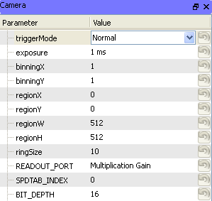
The Manager user interface for cameras typically consists of a simple list of parameters which define the current state of the camera. A standard set of parameters are available for all types of camera, including:
triggerMode determines how the camera will decide when to begin frame exposures. Values are:
- Normal a software signal begins frame acquisition, and the camera automatically determines when each frame exposure occurs.
- TriggerStart a hardware trigger initiates frame exposure, and the camera automatically determines when each subsequent frame exposure occurs.
- Strobe a hardware trigger initiates each frame exposure. The length of exposures is set by the exposure parameter.
- Bulb A hardware trigger initiates each frame exposure, and the length of the TTL pulse determines the exposure time for each frame.
exposure the current per-frame exposure time
binning the number of sensor pixels that should be binned together to produce one output pixel.
region sets the region of interest on the sensor. Using a smaller region can result in faster frame transfer from the camera.
Each camera driver implements extra parameters depending on the features available on the camera.
Task Runner Interface
The TaskRunner interface for Camera devices appears as a dock in the Task Runner module when a Camera device is selected in the device list. This interface allows the design of triggering waveforms and recording parameters for executing tasks.
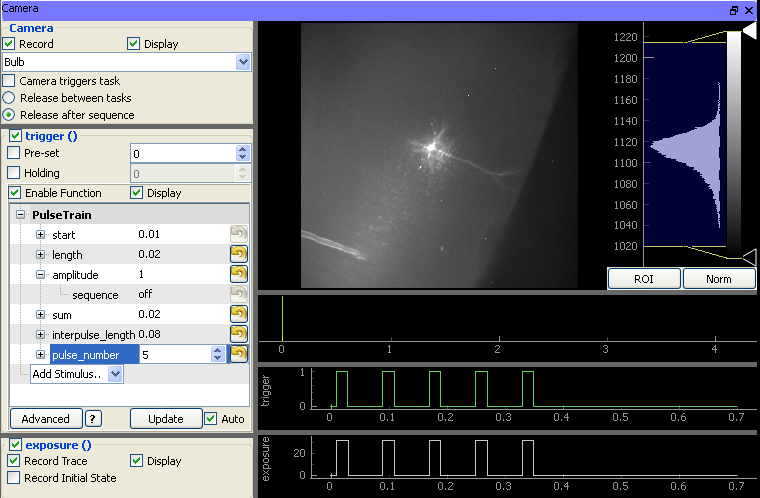
The interface is composed of two main sections:
- The left pane contains all of the controls that define the desired behavior of the camera during task execution:
- Camera group:
- Record: If unchecked, the camera will not record frames during the task. This is used to temporarily disable the camera in tasks combining multiple devices.
- Display: If unchecked, results from the camera are recorded but not displayed. This can improve performance during repeated tasks that require low latency from one execution to the next.
- Trigger mode: Specifies the desired triggering mode of the camera. Different camera types will support different modes. However, some common types are typically supported (described above).
- Camera triggers task: If the camera is being used to trigger other devices (usually a DAQ), this box must be checked to ensure that the camera is started after all other devices.
- Release between tasks and Release after sequence: Amongst the devices supported in ACQ4, cameras usually take longer to start than any others. For tasks that must repeat quickly, it is thus desirable that the camera should be started only once at the beginning of the sequence and reserved until the sequence is complete (Release after sequence). On the other hand, for sequences that run with a long delay between tasks it is often desirable to allow the camera to free-run in between task executions (Release between tasks).
Trigger group: Contains a standard function generator allowing the task to specify any arbitrary waveform with which to trigger the camera. Note that this will only have an effect if an appropriate Trigger mode is selected.
Exposure group: Controls determining whether the camera’s exposure signal should be recorded and displayed.
- The right pane contains:
- An image viewer (top) that displays imaging data returned from the camera during task execution.
- Two plot areas displaying the output triggering waveform (middle) generated by the DAQ and the input exposure signal (bottom) recorded by the DAQ.
Stored data format
Camera tasks that store to disk will generate a folder containing:
- A ‘frames.ma’ MetaArray file with a 3-dimensional array having axes (Time, X, Y). This file will have metadata indicating the camera parameters in use, the current optomechanical state of the device hierarchy (including information about objective lenses), and transformation information that unambiguously relates the stored image pixel coordinates to the global coordinate system. The timing of each frame is stored as axis-values, and a
preciseTimingvalue indicates whether the exposure or triggering waveforms were used to determine precise frame times.- A ‘channels.ma’ MetaArray file containing the triggering and exposure waveforms, and metadata related to the DAQ configuration.